At netcup I still had two idle VMs of the type VPS 1000 ARM G11 NUE. Their only purpose so far was to serve an authoritative DNS zone with bind9 running in Docker. Both machines come with 4 vCPUs and 8 GB of RAM, so they are a good fit for some experiments. The idea is to set up k3s on them and use bind9 to serve the authoritative DNS zone.
What interests me most is the new Kubernetes Gateway API. In addition to HTTPRoute, it also introduces UDPRoute and TCPRoute resources. These are still marked as experimental (see here), but I plan to cover them in a later blog post.
First, the VPSs need to be prepared so that k3s can be installed. With only two servers, high availability cannot be guaranteed. However, the same approach can be extended to a third server in order to achieve HA. So let’s delve into wireguard and k3s to create a cluster!
(This post is inspired by WesleyCh3n)
WireGuard
Both servers communicate with each other through a secure tunnel using WireGuard. This means we first need to ensure that both servers can communicate in both directions. The first step is to install WireGuard.
sudo apt-get update && sudo apt install wireguard
WireGuard uses public-key cryptography, so each server requires its own key pair. After installation, WireGuard provides a CLI tool to generate these keys.
wg genkey | tee private.key | wg pubkey public.key
Next, we create a WireGuard configuration on both servers. For simplicity, let’s call the first server VPS1 and the second VPS2. The configuration files are placed under /etc/wireguard/wg0.conf on each server. Since the private keys are stored in plaintext within the configuration file, I restricted access to root only with read and write permissions.
VPS1:
[Interface]
Address = 192.168.100.1
PrivateKey = <your-privkey>
ListenPort = 51820
PostUp = /etc/wireguard/add-nat.sh
PostDown = /etc/wireguard/del-nat.sh
MTU = 1420

[Peer]
PublicKey = <your-pubkey>
AllowedIPs = 192.168.100.0/24
Endpoint = <peer-public-ip>:51820
PersistentKeepalive = 25
VPS2:
[Interface]
Address = 192.168.100.2/24
PrivateKey = <your-privkey>
ListenPort = 51820
PostUp = /etc/wireguard/add-nat.sh
PostDown = /etc/wireguard/del-nat.sh
MTU = 1420

[Peer]
PublicKey = <your-pubkey>
AllowedIPs = 192.168.100.0/24
Endpoint = <peer-public-ip>:51820
PersistentKeepalive = 25
NAT
Attentive readers may have already noticed that there is a script for both PostUp (/etc/wireguard/add-nat.sh) and PostDown (/etc/wireguard/del-nat.sh).
Let’s walk through each of them together.
add-nat.sh
#!/bin/bash
IPT="/usr/sbin/iptables"

IN_FACE="eth0"                   # NIC connected to the internet
WG_FACE="wg0"                    # WG NIC
SUB_NET="192.168.100.0/24"       # WG IPv4 sub/net aka CIDR
WG_PORT="51820"                  # WG udp port

## IPv4 ##
$IPT -t nat -I POSTROUTING 1 -s $SUB_NET -o $IN_FACE -j MASQUERADE
$IPT -I INPUT 1 -i $WG_FACE -j ACCEPT # accept incomming traffic on wireguard interface
$IPT -I FORWARD 1 -i $IN_FACE -o $WG_FACE -j ACCEPT # forward incomming traffic to wireguard interface
$IPT -I FORWARD 1 -i $WG_FACE -o $IN_FACE -j ACCEPT # wirguard route to internet facing interface
$IPT -I INPUT 1 -i $IN_FACE -p udp --dport $WG_PORT -j ACCEPT # wireguard port accept
That script configures our server to act as a WireGuard VPN gateway using iptables. It assumes the server has two network interfaces: one facing the internet (eth0 in the example) and one virtual interface created by WireGuard (wg0). The VPN subnet is defined as 192.168.100.0/24, and WireGuard itself listens on UDP port 51820.
The script is executed on Wireguards startup, it sets up network address translation (NAT) so that traffic originating from VPN clients is rewritten with the server’s public IP before going out to the internet. This makes all client traffic appear as if it comes from the server, which is how VPN tunneling works. It also configures forwarding rules so that traffic can flow in both directions: from VPN clients out to the internet, and from the internet back to VPN clients. To make the tunnel possible in the first place, the script opens the WireGuard port on the internet-facing interface so that handshake and encrypted packets can arrive at the server.
Conversely, the script del-nat.sh just removes the entries we added to the iptables once Wireguard shuts down.
#!/bin/bash
IPT="/usr/sbin/iptables"

IN_FACE="eth0"                   # NIC connected to the internet
WG_FACE="wg0"                    # WG NIC
SUB_NET="192.168.100.0/24"       # WG IPv4 sub/net aka CIDR
WG_PORT="51820"                  # WG udp port

## IPv4 ##
$IPT -t nat -D POSTROUTING -s $SUB_NET -o $IN_FACE -j MASQUERADE
$IPT -D INPUT -i $WG_FACE -j ACCEPT
$IPT -D FORWARD -i $IN_FACE -o $WG_FACE -j ACCEPT
$IPT -D FORWARD -i $WG_FACE -o $IN_FACE -j ACCEPT
$IPT -D INPUT -i $IN_FACE -p udp --dport $WG_PORT -j ACCEPT
Enable IPv4 Forwarding
By default, Linux does not forward packets between interfaces. Enabling IPv4 forwarding via
sudo sysctl -w net.ipv4.ip_forward=1
allows the kernel to route traffic like a gateway. For WireGuard, this is required so that VPN clients on wg0 can access the internet or other networks through the server’s external interface (eth0). Without it, clients would only be able to reach the server itself.
Connect both Servers
On both servers, we can now activate the Wireguard links.
sudo wg-quick up wg0
We can check the status of the Wirguard interface
sudo wg show
It should output something like this.
interface: wg0
  public key: <your-pubkey>
  private key: (hidden)
  listening port: 51820

peer: <redacted>
  endpoint: <peer-public-ip>:51820
  allowed ips: 192.168.100.0/24
  latest handshake: 1 minute, 27 seconds ago
  transfer: 281.55 GiB received, 192.43 GiB sent
  persistent keepalive: every 25 seconds
We can also validate the connectivity between both servers via netcat.
On VPS2:
nc -l 48500
On VPS1:
nc 192.168.100.2 48500
If you sent for example the text sent, it should be displayed on VPS2. Congratulations, you established a working VPN!
Make Wireguard Interfaces Persistent
Now let’s make the Wireguard links persistent, so they startup on everytime the machine boots.
sudo systemctl enable wg-quick@wg0.service
sudo systemctl start wg-quick@wg0.service
Install k3s
k3s is quite easy to install. First, we initiate the master node (in this case on VPS1).
curl -sfL https://get.k3s.io | sh -s - \
    --write-kubeconfig-mode 644 \
    --disable servicelb \
    --disable traefik \
    --node-external-ip 89.58.33.132 \
    --node-ip 192.168.100.1 \
    --advertise-address 192.168.100.1 \
    --flannel-iface wg0 \
    --cluster-init
Now we get the node token.
sudo cat /var/lib/rancher/k3s/server/node-token
And initiate k3s on the secondary node (VPS2).
curl -sfL https://get.k3s.io | sh -s - \
    --server https://192.168.100.1:6443 \
    --token <your-token> \
    --write-kubeconfig-mode 644 \
    --disable servicelb \
    --disable traefik \
    --write-kubeconfig-mode 644 \
    --node-external-ip 152.53.1.216 \
    --node-ip 192.168.100.2 \
    --advertise-address 192.168.100.2 \
    --flannel-iface wg0
That`s it. Now you can use kubectl. For example, you should see two nodes in your cluster.
kubectl get nodes -o wide
should result in
NAME    STATUS   ROLES                       AGE   VERSION        INTERNAL-IP     EXTERNAL-IP    OS-IMAGE                         KERNEL-VERSION   CONTAINER-RUNTIME
VPS1    Ready    control-plane,etcd,master   10s   v1.32.6+k3s1   192.168.100.1   <VPS1-ip>   Debian GNU/Linux 12 (bookworm)   6.1.0-37-arm64   containerd://2.0.5-k3s1.32
VPS2    Ready    control-plane,etcd,master   10s   v1.32.6+k3s1   192.168.100.2   <VPS2-ip>   Debian GNU/Linux 12 (bookworm)   6.1.0-37-arm64   containerd://2.0.5-k3s1.32
Prevent Exposure of Node Ports
Kubernetes exposes NodePorts by default in the range 30000–32767.
For more details, see the official documentation.
It’s important to note that NodePorts are not only created when you explicitly define a Service of type NodePort, but also implicitly — for example, for health checks. However, Kubernetes uses iptables to ensure proper networking. It also heavily relies on the INPUT chain in iptables.
Chain INPUT (policy DROP 21 packets, 980 bytes)
num   pkts bytes target                     prot opt in     out     source               destination
1    98571   35M KUBE-ROUTER-INPUT          0    --  *      *       0.0.0.0/0            0.0.0.0/0            /* kube-router netpol - 4IA2OSFRMVNDXBVV */
2     7008 2930K KUBE-PROXY-FIREWALL        0    --  *      *       0.0.0.0/0            0.0.0.0/0            ctstate NEW /* kubernetes load balancer firewall */
3    91013   34M KUBE-NODEPORTS             0    --  *      *       0.0.0.0/0            0.0.0.0/0            /* kubernetes health check service ports */
4     7008 2930K KUBE-EXTERNAL-SERVICES     0    --  *      *       0.0.0.0/0            0.0.0.0/0            ctstate NEW /* kubernetes externally-visible service portals */
5    91013   34M KUBE-FIREWALL              0    --  *      *       0.0.0.0/0            0.0.0.0/0
6        0     0 ACCEPT                     0    --  *      *       0.0.0.0/0            0.0.0.0/0            /* KUBE-ROUTER rule to explicitly ACCEPT traffic that comply to network policies */ mark match 0x20000/0x20000
7    21871 9313K ACCEPT                     17   --  eth0   *       0.0.0.0/0            0.0.0.0/0            udp dpt:51820
8    20501 7693K ACCEPT                     0    --  wg0    *       0.0.0.0/0            0.0.0.0/0
9    48641   17M ufw-before-logging-input   0    --  *      *       0.0.0.0/0            0.0.0.0/0
...
The INPUT chain in iptables defines how packets destined for the local server are processed.
It decides whether to accept, reject, or drop incoming traffic such as SSH, HTTP, or VPN connections.
In short, it is the firewall filter for traffic directed at the server itself.
Let’s look at the INPUT chain KUBE-NODEPORTS.
In this case, I deployed an Envoy-Gateway, and we can clearly see that all incoming traffic is accepted for the health check.
This effectively makes the health check reachable from the public Internet — which is a serious security concern.
 pkts bytes target     prot opt in     out     source               destination
    0     0 ACCEPT     6    --  *      *       0.0.0.0/0            0.0.0.0/0            /* gateway/envoy-gateway-VPS1-gateway-74f73539:http-80 health check node port */ tcp dpt:32269
    ...
Furthermore, Kubernetes continuously pushes its own chains to the top of the INPUT chain, which means they get evaluated before your custom rules. As a result, all incoming packets hit the Kubernetes rules first. To prevent unwanted access, we need to block traffic before the INPUT chain comes into play.
So let’s have a look at the processing flow of netfilter.
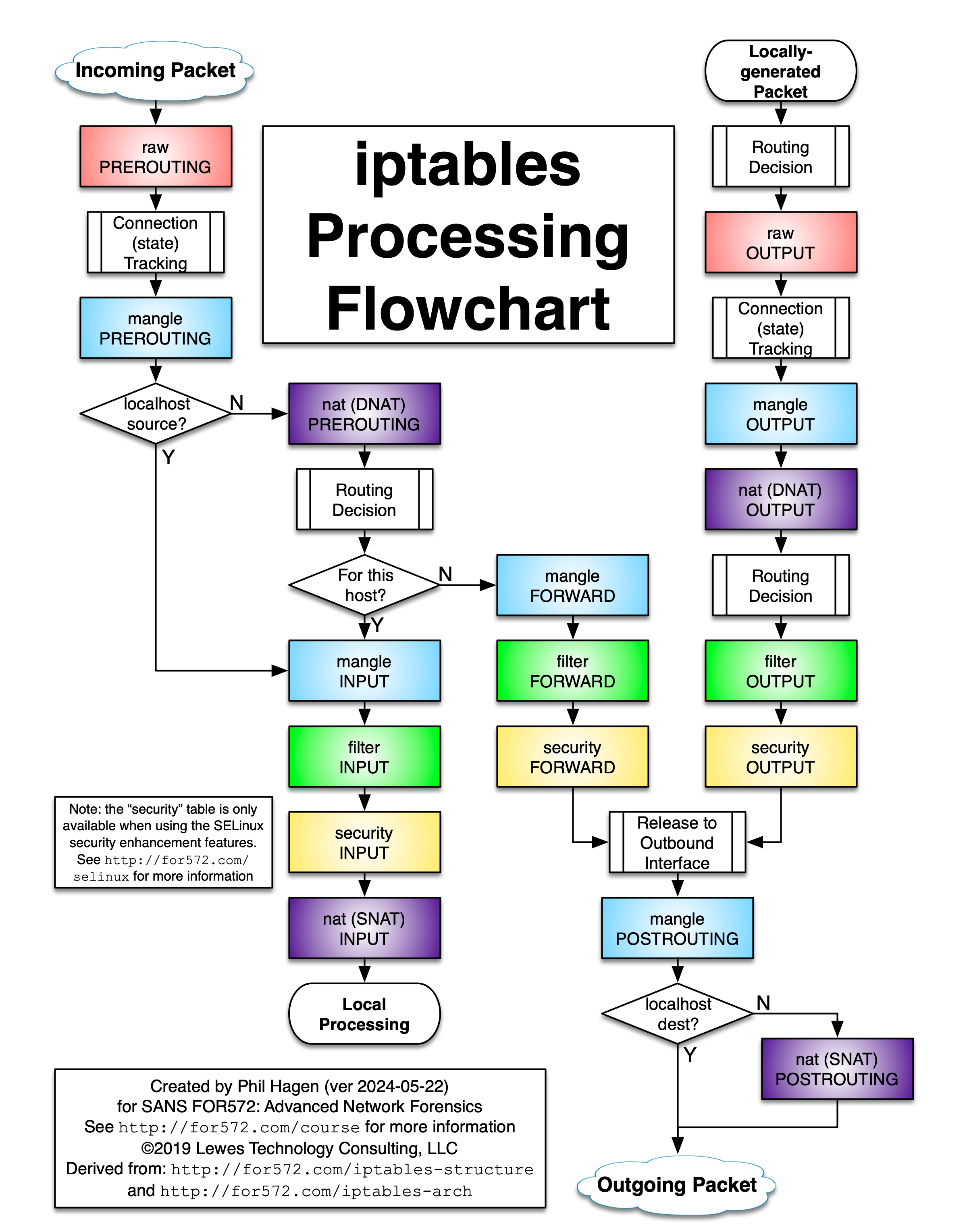
The key challenge is to block NodePort traffic originating from the Internet while still allowing legitimate traffic from Kubernetes itself (and the VPN). We don’t want to interfere with Kubernetes health checks.
To stay out of Kubernetes’ way, the best place to intercept this traffic is the raw PREROUTING table in iptables.
Here we can block all traffic on NodePorts that does not originate from Kubernetes.
Once traffic is accepted in netfilter, no further rules in the chain are evaluated.
For example, if traffic comes from Kubernetes (e.g.,10.42.0.0/16to port30001), it is accepted immediately and bypasses the rest of the chain.
#!/bin/bash
set -e

# Cleanup old chain and rules if any
iptables -t raw -D PREROUTING -j NODEPORT_FILTER 2>/dev/null || true
iptables -t raw -F NODEPORT_FILTER 2>/dev/null || true
iptables -t raw -X NODEPORT_FILTER 2>/dev/null || true

# Create custom chain
iptables -t raw -N NODEPORT_FILTER

# Allow traffic on node ports on wg0
iptables -t raw -A NODEPORT_FILTER -i wg0 -p tcp --dport 30000:32767 -s 10.42.0.0/16 -j RETURN # k3s pod nw
iptables -t raw -A NODEPORT_FILTER -i wg0 -p tcp --dport 30000:32767 -s 10.43.0.0/16 -j RETURN # k3s svc nw
iptables -t raw -A NODEPORT_FILTER -i wg0 -p tcp --dport 30000:32767 -s 192.168.100.0/24 -j RETURN # internal node traffic, adapt to your wg network

# drop everything else
# iptables -t raw -A NODEPORT_FILTER -p tcp --dport 30000:32767 -j LOG --log-prefix "NODEPORT DROP: " --log-level 4
iptables -t raw -A NODEPORT_FILTER -p tcp --dport 30000:32767 -j DROP

# Insert jump to custom chain at top of PREROUTING chain
iptables -t raw -I PREROUTING 1 -j NODEPORT_FILTER
As a test, deploy a simple Service in your cluster and run an nmap scan against your NodePort range from outside.
If your rules are configured correctly, nmap should report no open ports.
Hint: If you do not want to expose the Kubernetes API to the Internet (e.g., for kubectl), you may also deny incomming traffic on port
6443.